BTS Demag PDC Console Display Replacement
A replacement display can be an economical way to extend the service life of the PAT PDC unit installed in your crane.  Here at BTS we see many Demag customers with displays that are becoming unreadable, which poses a significant safety concern.  If you would like further information, or to see if your PDC unit qualifies for an upgrade display, please contact the BTS parts team toll-free in the US at 855.BODE.TEC or internationally at +1.303.433.8878 
 

Parts Store Free Quote


IMPORTANT NOTES

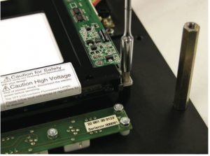
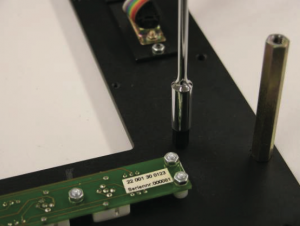
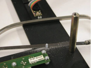
These instructions assume fundamental knowledge of mechanical and electrical systems. Please make certain to follow the precise order of steps in the instructions.  If you do not feel comfortable performing this procedure please contact one of the well qualified BTS Tech™ team members to assist you.  During the conversion, it will be necessary to remove the existing threaded pins with a saw.  Please make certain to prevent any chips and pieces from sawing from getting into any keyboard module that may be present.  Remove all chips immediately with a brush after sawing work is complete!


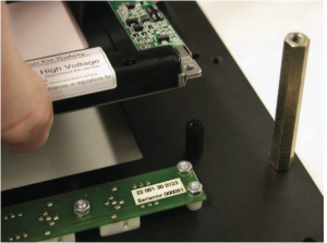
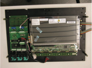
Your current PDC unit will have a white sticker on the inside of the unit with a “reference & material number.”  Please check that sticker against the following table to assure that your particular model is eligible for the upgrade.  

Reference Number Material Number
22 001 06 0011 600394
22 001 06 0013 603554
22 001 06 0016 603572
22 001 06 0019 603769
22 001 06 0022 603914
22 001 06 0027 604123
22 001 06 0034 604232
22 001 06 0038 604580
22 001 06 0039 604581
22 001 06 0042 604643


The following tools are required for conversion and are not included in the conversion kit

  • Screwdriver, Phillips recessed head
  • 5-mm and 6-mm hexagon keys
  • Small hand saw with metal or universal saw blade
  • Drill with 3.5 mm HSS drill bit
  • Small brush for removing metal chips

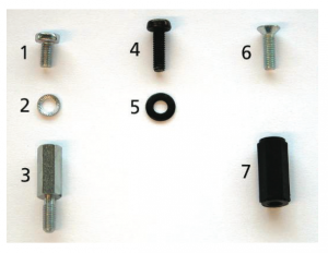
Conversion kit includes

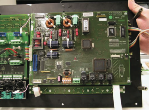
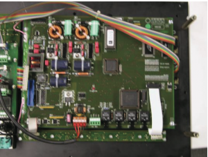
  • 1x electronics module
  • 1x display, TFT
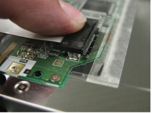
  • 1x flexible foil cable, 31-pin
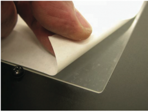
  • 1x anti-glare plexiglass plate
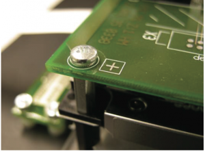
  • 4x rounded head screws M3 x 6 (#1)
  • 4x lock washers S3 (#2)
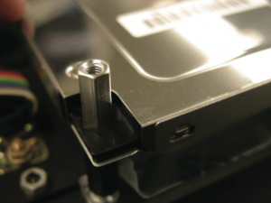
  • 4x spacing bolts M3 x 12, with threaded pin on one side (#3)
  • 4x rounded head screws M3 x 10, black (#4)
  • 4x washers 3.2, black (#5)
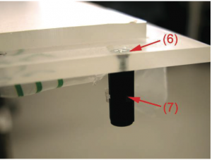
  • 4x counter sunk screws M3 x 10 (#6)
  • 4x spacing bolts M3 x 15, black (#7)
  • 1x tube of silicone adhesive 744 or 737

Bode Technical Services PDC Display 2


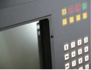
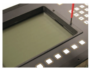
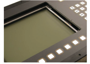
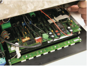
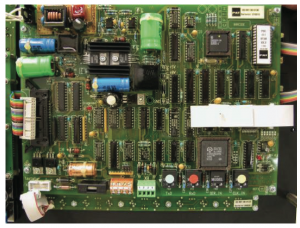
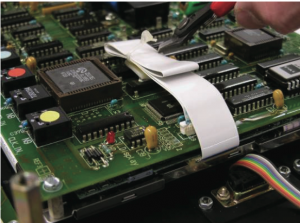
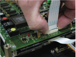
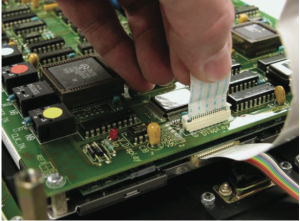
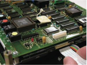
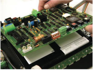
PDC Console Display Update Instructions

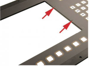
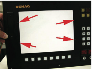
This following images detail all required steps illustrated on a sample console.

Bode Technical Services PDC Display 3
Using a Phillips screwdriver, unscrew the 4 screws on the screen lip.
Bode Technical Services PDC Display 4
Remove the screen lip.
BTS PDC Repair 5
Place the console with front on the work table. Loosen and remove the screws. Then remove the housing cover. Loosen the screws for the individual wires of the power supply line. Then remove the wires. Wire colours: 1=rd / 2=or / 3=bn / 4=bl Remove 4 fibre optical plugs.
Bode Technical Services PDC Display 6
Remove the remaining plug connections.
Bode Technical Services PDC Display 7
Undo the cable tie on the ribbon cable.
Bode Technical Services PDC Display 8
Pull the locking frame up.
Bode Technical Services PDC Display 9
Remove the ribbon cable.
Bode Technical Services PDC Display 10
Loosen the other side of the ribbon cable as well. Then remove the locking frame.
Bode Technical Services PDC Display 11
Loosen the 4 screws and take out the module.
Bode Technical Services PDC Display 12
Using a (5-mm) socket wrench, remove the 4 hexagon bolts.
Bode Technical Services PDC Display 13
Remove the display.
Bode Technical Services PDC Display 14
Remove the 4 spacing bolts with a (5-mm) socket spanner.
Bode Technical Services PDC Display 15
Using a hand saw, saw off the 4 threaded pins as flush as possible against the front plate (max. overhang 1 mm). • Make certain to remove all sawing chips completely with a small brush!
Bode Technical Services PDC Display 16
Prepare the plexiglass plate from the conversion kit with counter sunk screw (6) and spacing bolts, black (7) as shown.
Bode Technical Services Demag PDC Display 17
Drill out the four threadings that are present with a drill and 3.5-mm bit.
Bode Technical Services Demag PDC Display 18
Set the plexiglass plate in place on the back (with the milling groove on the left) and …
Bode Technical Services Demag PDC Display 19
…using the four rounded head screws (4) with washers under them (5) mount on the front.
Bode Technical Services Demag PDC Display 20
Remove the protective film from the new display and on the back of the plexiglass.
BTS Demag PDC Display Replacement 21
Set the new display in place on the spacing bolts…
BTS Demag PDC Display Replacement 22
…and fasten with four spacing bolts (3).
BTS Demag PDC Display Replacement 23
Snap the plug of the new flexible foil cable in place on the display motherboard and then secure it with a sufficient amount of silicone adhesive to prevent it from falling out.
BTS Demag PDC Display Replacement 24
Place the new electronics module on the bolts as shown…
BTS Demag PDC Display Replacement 25
…and fasten with four screws (1) and a washer (2) under each.
BTS Demag PDC Display Replacement 26
Reconnect the remaining plugs in the appropriate positions and lock them into place. • Reconnect the power supply cable. Wire colours: 1=rd / 2=or / 3=bn / 4=bl • Connect the fibre optical plug in the same positions as for the old module. • Finally, snap the plug of the new flexible foil cable in place on the electronics module and then secure it with a sufficient amount of silicone adhesive to prevent it from falling out.
BTS Demag PDC Display Replacement 27
Check the connections one more time to ensure they are securely seated. • Reassemble the housing cover. • Check the device for functionality. • After the console is assembled, remove the protective display film on the front.


PDF Copy

CLICK HERE

PDC Screen Replacement

These instructions based on Hirschmann Automation and Control GmbH • Mobile Machine Control Solutions • www.beldensolutions.com 2 22-001-19-0165_420487_en.doc / 2012-03-13 / Rev. B / rk.

Bode Technical Services Inc does not give any warranty for this material, including any implied warranty of marketability or fitness for a particular purpose.  Bode Technical Services Inc is not liable for any errors in the contents of the material, or for any direct or indirect damage in connection with the provision and the use of this information.